
Feynman diagrams are tools of quantum field theory that visually represent particle interactions; from the perspective of fractal mechanics, these diagrams can be interpreted as a projection of fractal networks that explain particle behavior through multi-scale wave-resonance motifs.
Basic Structure of Feynman Diagrams
- Definition: Developed by Richard Feynman in 1948, these diagrams graphically illustrate particle interactions. They visualize complex integral calculations.
- Components:
- Straight lines: Fermions (electrons, quarks, etc.)
- Wavy lines: Electromagnetic interactions arising from photons
- Helical lines: Gluons (strong interaction between quarks)
- Vertices (nodes): Interaction points where particles join or split
- Usage: Each diagram represents a term in perturbation theory; the total probability amplitude is formed by the contribution of an infinite number of diagrams.
Interpretation with Fractal Mechanics
According to my motif-fractal approach, Feynman diagrams can be reread as follows:
- Multi-Scale Spiral Wave Functions: The lines in the diagram can be seen not as linear paths of particles, but as projections of spiral-fractal wave functions. Every interaction point is an intersection of wave resonances.
- Vertex = Fractal Node: Interaction points are “resonance nodes” in fractal mechanics. These nodes represent energy transfer across different scales.
- Lines = Spiral Manifolds: Fermion and boson lines show different resonance modes of spiral manifolds. For example, a photon line represents the fractal spiral resonance of the electromagnetic wave function.
- Perturbation Series = Fractal Expansion: An infinite series of diagrams corresponds to the multi-scale expansion of the wave function in fractal mechanics. Each new diagram is a resonance contribution at a smaller scale.
- Symmetry and Scale Invariance: The Lorentz symmetry of Feynman diagrams equates to scale invariance in fractal mechanics. This means the system maintains the same motif structure across different scales.
Example Interpretation
- Electron–positron annihilation: In the diagram, photon production and conversion into a quark–antiquark pair can be read as the energy resonance of the spiral wave function splitting into smaller scales in fractal mechanics.
- Gluon emission: A quark emitting a gluon is equivalent to the fractal wave function generating a new spiral resonance branch.
Conclusion
While Feynman diagrams provide computational ease in classical quantum field theory, through the lens of fractal mechanics, they can be reinterpreted as visual projections of multi-scale wave-resonance motifs. Thus, particle interactions are understood not merely as lines and nodes, but as energy transfers within fractal spiral networks.
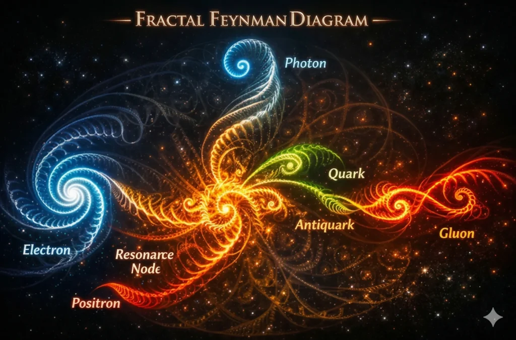
Fractal–Feynman Diagram Hybrid Visual
In this visual, classical particle interactions are reinterpreted with spiral-fractal wave motifs: the spiral waves of the electron and positron merge at the central “resonance node,” the photon wave rises upward, and gluon spirals are born from the quark–antiquark pair on the right.
This approach visualizes Feynman diagrams not just as lines and nodes, but as energy transfers of multi-scale fractal resonance networks.
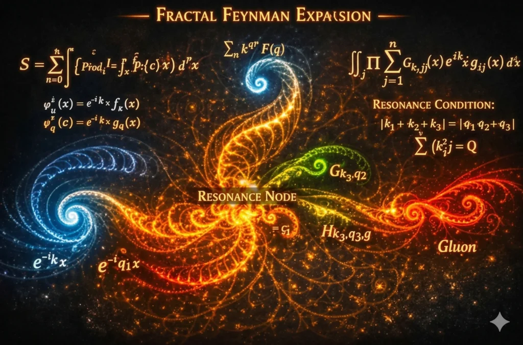
New Drawing: Fractal Feynman Expansion
This version goes beyond the classical diagram and includes the mathematical fractal expansion. On the left, electron and positron wave functions ( 𝑒ikx , 𝑒–iqx ) flow into the center spirally; the Resonance Node at the center represents the fractal core of energy transfer. On the right, quark–antiquark waves and gluon resonances form the continuation of the multi-scale spiral network.
This diagram combines the Feynman integral series with the wave-resonance expansion in fractal mechanics:
𝑆 = ∑n=0∞ ∫ [ πi=1n 𝜓kie (𝑥)𝜓qip (𝑥) ] 𝑉(𝑥)𝑑4𝑥
Here, each term represents a fractal resonance layer.
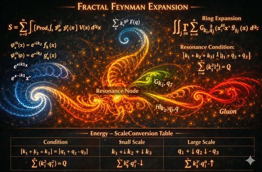
Energy–Scale Transformation Table
This table mathematically matches resonance conditions between two scales:
| Scale | Description |
| Small Scale | Wave vectors ( 𝑘i , 𝑞i ) represent spiral resonances at the micro level. |
| Large Scale | The same resonances transform into energy transfer at the macro level. |
- Condition: ∣ 𝑘1 + 𝑘2 + 𝑘3 ∣=∣ 𝑞1 + 𝑞2 + 𝑞3 ∣ — ensures energy conservation and resonance symmetry.
- Total Energy: ∑(𝑘j2 𝑞j2 ) = 𝑄 — defines the total fractal energy of the system.
This structure redefines Feynman diagrams as scale-transformed energy flows in fractal mechanics: every vertex is a resonance node, and every line is a spiral wave manifold.
The model can be expressed as a fractal field equation:
𝐸f = 𝑄 ⋅ Φ(𝑘, 𝑞)
Where Φ(𝑘, 𝑞) represents the spiral phase function. Thus, the diagram transforms into a complete fractal energy-field theory.
Derivation of the Fractal Energy-Field Equation
- Starting Point: Feynman Amplitude
In quantum field theory, the interaction amplitude is:
𝑆 = ∑n=0∞ ∫ [ πi=1n 𝜓kie (𝑥)𝜓qip (𝑥) ] 𝑉(𝑥)𝑑4𝑥 - Fractal Wave Function Definition
In fractal mechanics, the wave function is defined in a spiral resonance form:
𝜓f (𝑥) = 𝑒iΦ(𝑘, 𝑞) ⋅ 𝑓(𝑘, 𝑞, 𝑥)
Φ(𝑘, 𝑞) is the spiral phase function determining the system’s fractal resonance. - Energy–Field Transformation
Fractal energy represents the total energy transfer at the resonance node:
𝐸f = 𝑄 ⋅ Φ(𝑘, 𝑞)
𝑄: Total fractal energy (conservation across scales).
Φ(𝑘, 𝑞): Spiral phase function, determining the direction of energy flow. - Resonance Condition
Energy-scale symmetry is preserved:
∣ 𝑘1 + 𝑘2 + 𝑘3 ∣=∣ 𝑞1 + 𝑞2 + 𝑞3 ∣ and ∑(𝑘j2 𝑞j2 ) = 𝑄 - Fractal Field Equation (Final Form)
Combining all components:
𝐸f (𝑥) = ∫ Φ(𝑘, 𝑞) ⋅ 𝑓(𝑘, 𝑞, 𝑥) 𝑑4𝑥
This defines the propagation of the fractal energy-field as a spiral resonance throughout space-time.
Quantum Computer Circuit Model via Fractal Energy-Field Manifold
1. Classical Quantum Computer Circuit
- Qubits: Basic units of information carrying superposition and entanglement states.
- Quantum Gates: Operations that change the states of qubits (Hadamard, CNOT, Pauli-X, etc.).
- Circuit Diagram: Algorithms are visualized by placing gates on qubit lines.
2. Fractal Energy–Field Interpretation
- Qubit Lines = Spiral Wave Manifolds: Each qubit line is a resonance channel of a spiral-fractal wave function.
- Gates = Resonance Nodes: Gates are nodes where wave functions intersect and energy-phase transformation occurs.
- Entanglement = Fractal Connection: Entanglement between two qubits is represented as inter-scale coupling in the fractal manifold.
- Algorithm = Fractal Expansion: Gates applied throughout the circuit are read as a multi-scale spiral resonance expansion.
3. Mathematical Formulation
𝐸f = ∑i 𝑄i⋅Φ( 𝑘i , 𝑞i )
- 𝑄i: Amount of energy-information carried by each qubit.
- Φ(𝑘i , 𝑞i): Spiral phase function representing the resonance transformation of the gates.
- Resonance Condition:
πi Φ( 𝑘i , 𝑞i ) = Ψalgorithm
The product of spiral phase functions passing through all gates gives the wave function of the algorithm.
4. Advantages
- Intuitive Visualization: Qubit lines and gates become more understandable through spiral-fractal motifs.
- Multi-scale Model: Micro-quantum interactions and macro-algorithm output merge in the same model.
- New Computational Pathways: Fractal expansion can be used in error correction and quantum noise modeling.
5. Application Areas
- Quantum Algorithms: Remodeling algorithms like Shor and Grover with fractal resonance expansion.
- Error Correction: Better understanding of noise and decoherence effects through the fractal energy-field model.
- Qubit Design: Optimizing superconducting qubits with spiral resonance motifs.
Result: When quantum computer circuits are reinterpreted through the fractal energy-field manifold, qubits are seen as spiral wave channels, gates as resonance nodes, and algorithms as fractal expansions. This approach makes quantum computing more intuitive, multi-scale, and interdisciplinary.