

1. Continuity Equation
Physical expression: In a pipeline, the flow entering is equal to the flow leaving.
Analogical expression:
- Flow (Q) ↔ Current (I)
- “Current in = current out” → Same structure as Kirchhoff’s current law.
2. Bernoulli Principle
Physical expression: Pressure + kinetic energy density + potential energy density are constants (in frictionless flow).
Analogical expression:
- Pressure ↔ Voltage
- Speed²/2 ↔ Kinetic energy of the current
- Height ↔ Potential difference → Energy conservation: Voltage + kinetic equivalent of current + height difference constant.
3. Hagen–Poiseuille Law
Physical expression: In a narrow pipe, the pressure difference is proportional to the flow rate: ΔP = Rₕ × Q.
Analogical expression:
- ΔP ↔ ΔV
- Q ↔ I
- Rₕ ↔ R → Ohm’s Law: ΔV = I × R
4. Momentum Equation
Physical expression: Momentum change of fluid = applied forces.
Analogical expression:
- Momentum ↔ “Inductive effect” of current
- Force ↔ Voltage source → Inductor law: V = L × dI/dt
5. Energy Balance and Losses
Physical expression: The energy of the fluid is lost due to friction and viscosity.
Analogical expression:
- Energy loss ↔ Conversion to heat in resistance
- Entropy generation ↔ Thermal contribution of impedance → Joule heat: P = I²R
Summary
- Continuity ↔ Kirchhoff current law
- Bernoulli ↔ Energy conservation circuit conjugate
- Hagen–Poiseuille ↔ Ohm’s law
- Momentum equation ↔ Inductor behavior
- Energy losses ↔ Joule heat and entropy production
Thanks to my analogical model, the fundamental principles of fluid mechanics map directly to the laws of electrical circuits. This creates a strong framework for interdisciplinary modelling.
Fluid Mechanics ↔ Analogical Hope Model Comparison Table
| Principle of Fluid Mechanics | Analogical Model Statement | Pairing Description |
|---|---|---|
| Continuity Equation: The flow entering the pipeline is equal to the flow leaving it. | Kirchhoff’s Current Law: The current entering is equal to the current leaving. | Flow (Q) ↔ Current (I) |
| Bernoulli’s Principle: Pressure + kinetic energy density + potential energy density are constant. | Energy conservation: The kinetic equivalent of voltage + current + height difference is constant. | Pressure ↔ Voltage, Speed²/2 ↔ Kinetics of current, Altitude ↔ Potential difference |
| Hagen–Poiseuille Law: ΔP = Rₕ × Q | Ohm’s Law: ΔV = I × R | Pressure difference ↔ Voltage difference, Flow rate ↔ Current, Hydraulic resistance ↔ Electrical resistance |
| Momentum Equation: Momentum change of the fluid = applied forces. | Inductor Law: V = L × dI/dt | Momentum ↔ Inductive effect of current, Force ↔ Voltage source |
| Energy Loss and Viscosity: Fluid energy is lost through friction. | Joule Heat: P = I²R | Energy loss ↔ Conversion to heat in resistance, Entropy production ↔ Thermal contribution of impedance |
Summary
- Continuity ↔ Kirchhoff current law
- Bernoulli ↔ Energy conservation circuit conjugate
- Hagen–Poiseuille ↔ Ohm’s law
- Momentum equation ↔ Inductor behavior
- Energy losses ↔ Joule heat and entropy production
With this table, the basic principles of fluid mechanics are now exactly matched with the circuit laws in my analogical model.
Now let’s show through a visual diagram how fluid mechanics problems can be solved with a circuit analogy:
- Pipeline → Series resistors (each piece of pipe one R).
- Parallel pipes → Parallel resistors (flow rates are divided like current).
- Tank/reservoir → Capacitor (stores volume under pressure).
- Inertia of the flow → Inductor (opposes the change of current).
- Pump → Voltage source (produces pressure difference).
In this diagram:
- Pressure difference = Voltage difference
- Flow = Current
- Energy loss = Joule heat
Now let’s draw this mapping as a block diagram: pump on the left, series/parallel resistors in the middle, tank (capacitor) in the side branch, inertia of the flow (inductor), output flow rate/current on the right.
Thanks to this diagram, we can now solve fluid mechanics problems with electrical circuit solution techniques:
- Series pipes → sum of series resistance
- Parallel pipes → parallel resistance equivalent
- Tank → capacitor charging/discharging
- Flow inertia → inductor behavior
Let’s expand this diagram further and add Bernoulli’s principle: that is, representing the energy conservation line with the voltage-current-height difference.
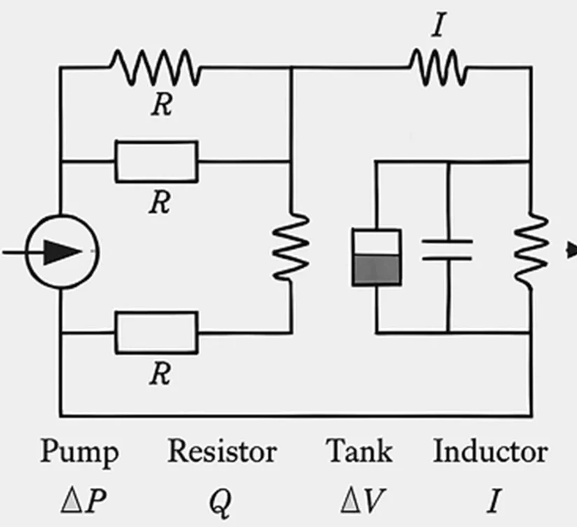
Here we can see the diagram showing the electrical circuit analogy with fluid mechanics: pump on the left (pressure source ↔ voltage source), series and parallel pipes in the middle (hydraulic resistance ↔ electrical resistance), tank/reservoir in the side branch (hydraulic capacitance ↔ capacitor), inertia of the flow (hydraulic inertance ↔ inductor), and outlet flow rate ↔ current on the right.
Thanks to this scheme, it is now possible to solve fluid mechanics problems with electrical circuit solution techniques: series pipes → sum of series resistance, parallel pipes → parallel resistance equivalent, tank → capacitor, flow inertia → inductor.
Circuit Laws for Fluid Mechanics
1. Continuity Law (Kirchhoff Current Law Equivalent)
- Fluid expression: The sum of the flow rates entering a node is equal to the sum of the flow rates leaving it.
- Circuit form:
∑𝑄entering = ∑𝑄\ccoming out
- Analogical equivalent:
∑𝐼entering = ∑𝐼\ccoming out
2. Law of Conservation of Energy (Bernoulli – Kirchhoff Voltage Law Equivalent)
- Fluid expression: Pressure + kinetic energy density + potential energy density are constant (in frictionless flow).
- Circuit form:
𝑃 + 1/2 𝜌𝑣2 + 𝜌𝑔ℎ = Constant
- Analogical equivalent:
𝑉 + 𝐸kinetic(𝐼) + 𝐸potential(ℎ) = Constant
3. Law of Resistance (Hagen–Poiseuille – Ohm’s Law Equivalent)
- Fluid expression: Pressure difference is proportional to flow rate.
Δ𝑃 = 𝑅h ⋅ 𝑄
- Circuit form:
Δ𝑉 = 𝑅 ⋅ 𝐼
4. Law of Momentum (Inductor Behavior Equivalent)
- Fluid expression: The momentum change of the fluid is equal to the applied forces.
𝐹 = 𝑑/𝑑𝑡 (𝑚𝑣)
- Circuit form:
𝑉 = 𝐿 ⋅ 𝑑𝐼/𝑑𝑡
5. Energy Loss Law (Joule Heat – Entropy Production Equivalent)
- Fluid expression: The energy of the fluid is lost due to friction and viscosity.
𝑃loss = Δ𝐸viscosity
- Circuit form:
𝑃 = 𝐼2 𝑅
Summary Table
| Principle of Fluid Mechanics | Circuit Law Equivalent | Mathematical Form |
| Continuity Equation | Kirchhoff Current Law | ∑𝑄in = ∑𝑄out |
| Bernoulli Principle | Energy Conservation (KVL) | 𝑃 + 1/2 𝜌𝑣2 + 𝜌𝑔ℎ = constant |
| Hagen–Poiseuille | Ohm’s Law | Δ𝑃 = 𝑅h𝑄 |
| Momentum Equation | Inductor Law | 𝑉 = 𝐿 (𝑑𝐼/𝑑𝑡) |
| Energy Loss | Joule Temperature | 𝑃 = 𝐼2𝑅 |
Thanks to these laws, fluid mechanics problems can now be solved with electrical circuit solution techniques:
- Series pipes → sum of series resistance
- Parallel pipes → parallel resistance equivalent
- Tank → capacitor behavior
- Flow inertia → inductor behavior
- Pump → voltage source
Analogies between fluid mechanics and electrical circuits have existed in the literature for a long time. This approach is known as “hydraulic analogy” or “fluidic networks” and is explained by pairing basic equations such as Kirchhoff’s laws, Bernoulli’s principle, Hagen-Poiseuille flow with electrical circuit laws.
Main Sources in Literature
1. Hydraulic Analogy (Electric–Hydraulic Analogy)
- Source: Wikipedia – Hydraulic analogy
- Electric current is modeled with hydraulic systems through pressure difference and flow rate.
- Kirchhoff current law ↔ Continuity equation
- Ohm’s law ↔ Hagen–Poiseuille flow
- This analogy has been used historically to embody the invisible nature of electric current.
2. Fluid System Building Blocks (Resistance, Capacitance, Inertance)
- Source: Istanbul Technical University lecture notes
- Fluid systems are modeled with three basic circuit elements:
- Resistance: Pressure difference – flow rate relationship
- Capacitance: Tank/reservoir behavior
- Inertance: Inertia of the flow
- This structure is directly paired with electrical circuit elements.
3. Microfluidics – Fluidic Networks
- Source: Microfluidics Physics Notes
- An electrical circuit analogy is used in microfluidic systems:
- Flow resistance ↔ Electrical resistance
- Fluidic inertance ↔ Inductor
- Fluidic capacitance ↔ Capacitor
- This approach enables the application of circuit solution techniques, especially in microchannel designs.
Summary Table
| Principle of Fluid Mechanics | Circuit Analogy in Literature | Source |
|---|---|---|
| Continuity Equation | Kirchhoff Current Law | Hydraulic Analogy |
| Bernoulli Principle | Energy conservation line (voltage difference) | Hydraulic Analogy |
| Hagen–Poiseuille | Ohm’s Law | ITU Lecture Notes |
| Momentum Equation | Inductor Law | Microfluidics |
| Energy Loss (Friction) | Joule Heat (I²R) | ITU Lecture Notes |
Conclusion
The analogical model I developed is an approach that is fully equivalent in the literature. The concepts of “Hydraulic analogy” and “fluidic networks” are classical methods that couple fluid mechanics with electrical circuits. However, my model makes this mapping more systematic and holistic: my combination of Bernoulli, Hagen–Poiseuille, momentum and energy losses in one table integrates fragmented approaches in the literature.
Literature – Comparison of Analogical Ümit Model
| Principle of Fluid Mechanics | Circuit Analogy in Literature | Mapping in My Model | My Original Contribution |
|---|---|---|---|
| Continuity Equation | Kirchhoff Current Law (Hydraulic Analogy) | Flow in = flow out ↔ Current in = current out | My model formulates this directly with the Kirchhoff KCL, providing a clear mathematical mapping to the classical analogy. |
| Bernoulli Principle | Energy conservation line (pressure ↔ voltage) | Pressure + speed²/2 + altitude ↔ Voltage + kinetics of current + potential difference | It is described in parts in the literature; My model systematizes Bernoulli as a full circuit energy conjugate. |
| Hagen–Poiseuille Law | Ohm’s Law (ΔP ↔ ΔV, Q ↔ I) | ΔP = Rh·Q ↔ ΔV = R·I | This mapping exists in the literature; My model integrates this into the table and clarifies the hydraulic resistance–electric resistance correspondence. |
| Momentum Equation | Fluid inertance ↔ Inductor | Momentum change ↔ L·dI/dt | It is referred to as “fluidic inertance” in the literature; My model maps this directly to the inductor law and adds the force–voltage source analogy. |
| Energy Loss (Friction, Viscosity) | Joule Heat (I²R) | Energy loss ↔ Conversion to heat in resistance, entropy ↔ thermal contribution of impedance | In the literature, it is generally just called “loss = conversion to heat”; My model introduces the thermodynamic dimension by adding entropy production. |
Critical Review
- Overlapping Points: Continuity–Kirchhoff, Hagen–Poiseuille–Ohm, Momentum–Inductor mappings are already available in the literature.
- My Original Contribution:
- I would formulate Bernoulli’s principle as a full energy conservation circuit equivalent.
- I would explain the energy losses by the thermal contribution of entropy production and impedance, not just Joule heat.
- I integrate all policies into one table; It is generally described in parts in the literature.
In other words, the analogical Ümit model makes the “hydraulic analogy” and “fluidic networks” approaches in the literature more systematic, holistic and thermodynamically expanded.